

How to Test a Landscape Lighting Circuit
Test the transformer first with a multimeter: if the output is below the tap rating by more than about 10% under load, the fault is likely upstream of the run. Guessing wrong can mean replacing good fixtures, digging up wire for no reason, or leaving a short that keeps killing bulbs. This guide shows how to check the transformer, cable run, splice points, and fixtures in a fast sequence before you pull a single cable or cut the ground.
Test the transformer first with a multimeter. If the output is more than about 10% below the tap rating under load, the fault is probably upstream of the run. Guessing wrong can mean replacing good fixtures, digging up wire for no reason, or leaving a short that keeps killing bulbs. This guide shows how to check the transformer, cable run, splice points, and fixtures in order before you pull a single cable or cut the ground.
What you’ll need


- Digital multimeter with AC voltage, resistance, and continuity modes
- Insulated screwdriver and basic hand tools
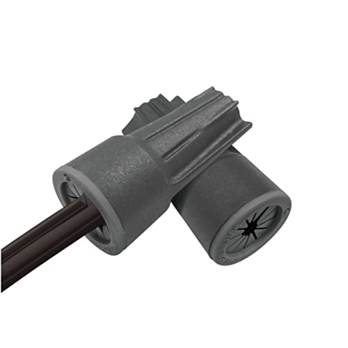
- Silicone-filled, outdoor-rated wire connectors
- Short fixture-to-transformer test leads
li>Flashlight, notebook, and replacement connectors
Start with the power source
Switch off the circuit at the breaker, then avoid touching any conductors until you confirm the circuit is dead. Check the exterior receptacle, timer, and transformer input first. Many low-voltage landscape systems use a transformer from 120V line voltage, and a dead GFCI outlet can make the whole circuit look failed when the low-voltage side is fine.
Check the GFCI and the transformer input
Find the GFCI-protected receptacle that feeds the transformer. Many jurisdictions require that protection for exterior transformer plugs. Reset the outlet if it has tripped, then confirm the transformer is receiving about 120V AC at its input terminals with the meter set to AC voltage.
If the transformer has no line voltage, stop there. The fault is upstream of the run. If line voltage is present, move to the low-voltage side.
What the first readings mean
A low-voltage outdoor lighting circuit is usually 12V AC, though some systems use 24V. On the output side, a normal transformer reading is within 10–14V for a standard 12V system, and many multi-tap transformers also provide 12V, 13V, 14V, and 15V taps. Below about 10V may suggest transformer trouble or overload.
What to test
Use a digital multimeter for voltage, resistance, and continuity testing. Match the mode to the circuit condition: AC voltage for live transformer checks, resistance or continuity only for de-energized conductors. A flashlight helps at the transformer box, and silicone-filled connectors belong in the repair pile if a splice is open to moisture.
How do you test the transformer output?
Measure the output terminals at the transformer with the meter set to AC voltage. Compare the reading to the tap setting in use. If the transformer is set to 12V and you read much less under load, the transformer may be failing or overloaded. If the reading is normal at the transformer, the problem is farther out in the run.
- Set the multimeter to AC volts.
- Touch the probes to the active output terminals.
- Record the reading at the transformer with the lights on.
- Compare that number to the selected tap, not to the wire length.
- If the reading is low, disconnect part of the load and recheck.
A 12V transformer may read about 12.8V with half the fixtures disconnected and about 9.6V with the full run connected. That pattern points to overload or a short on the circuit, not a bad meter reading.
How do you isolate the circuit run?
Split the run into halves to narrow the fault. If the transformer output is good but the lights are dead or weak past a certain point, divide the cable run and test one section at a time. Use continuity testing only on de-energized, isolated conductors.
- Turn off power and disconnect the run from the transformer.
- Separate the run at a midpoint splice or fixture junction.
- Test each half for continuity end to end.
- Check for an open wire, a short, or a damaged splice.
- Reconnect only the good half and retest under power.
On long runs, thinner cable makes voltage drop worse. Common wire sizes for outdoor lighting are 12, 10, and 8 AWG, and for runs over 50 feet, 12-gauge wire is recommended. Anything beyond 100 feet may need a dedicated circuit or a second transformer.
How do you tell a fixture from wiring?
Move a suspect fixture to a known-good lead, or connect it with a fixture-to-transformer test lead setup. That separates the lamp or LED module from the rest of the circuit. If the same fixture fails on the test lead, the fixture is the problem. If it works, the wiring or splice on the original leg is the fault.
- Disconnect the suspect fixture from the run.
- Attach it to a short known-good test lead from the transformer.
- Power the transformer and observe the fixture.
- If it lights normally, inspect the original splice and cable.
- If it stays dark or flickers, replace the fixture or internal module.
Suppose one path light goes out while the others stay lit. If the fixture works on a test lead, the problem is usually a loose splice or corrosion at that point, not the transformer.
Landscape lighting troubleshooting table
| Symptom | Multimeter test | Likely cause | Next action | Expected readings |
|---|---|---|---|---|
| Dead system | AC voltage at transformer input, then output terminals | Tripped GFCI, no line power, failed transformer | Reset the GFCI, confirm about 120V AC at input, then check output | Input: about 120V AC. Output: normal 12V system is within 10–14V; below 10V suggests failure |
| One dead fixture | Fixture on known-good test lead; continuity only with power off | Bad lamp, failed LED module, open splice | Swap the fixture to a test lead, then inspect the splice | Good fixture should light on the test lead; continuity should be present only on isolated conductors |
| Dim far-end fixtures | Voltage at transformer and at the last fixture at night | Voltage drop, thin wire, long run, overload | Compare the readings, then reduce load or upgrade cable gauge | Transformer output normal; far-end voltage noticeably lower than the transformer reading |
| Flicker after rain | Visual inspection first, then continuity on dry, isolated conductors | Moisture in a splice, corroded connector, damaged insulation | Open the splice, dry it out, replace with silicone-filled connectors | Continuity may come and go on a wet splice; the reading is only valid after isolation and drying |
| Breaker or GFCI trip | AC voltage at outlet, then isolate sections of the run | Short to ground, crushed cable, failed fixture | Disconnect sections until the trip stops, then inspect the last connected leg | About 120V AC at the outlet; low-voltage output may drop when the shorted leg is attached |
Common mistakes
Do not test continuity on energized conductors. That reading only means something when the circuit is dead and isolated. Also do not chase voltage drop before checking for loose or corroded connectors, because bad splices can mimic a long-run problem.
A common first-timer mistake is digging near the last fixture before measuring at the transformer and at the farthest fixture at night. Measure first. Dig later, if the readings point to a buried fault.
Another common miss is using undersized wire on a long run. Thin cable raises resistance, which increases voltage drop and leaves far-end fixtures dim or off-color. For longer runs, heavier cable is the correction, not a bigger bulb.
If that didn’t work, try this next
If the transformer output is normal and the run still fails, move outward in this order: splice points, fixture leads, then buried cable sections. Replace visibly damaged wire sections and any connector that shows corrosion, loose contact, or moisture intrusion. Use silicone-filled, direct-burial connectors for the repair.
- Open the first suspect splice.
- Inspect for cut, frayed, or improperly connected wires.
- Replace the connector, then retest the circuit.
- If the fault remains, move to the next splice or fixture.
- Stop digging once the failed section is identified.
Keep splices above water where possible, use direct-burial connectors, and avoid overloading the transformer. A 300W transformer may feed several runs totaling 240–270W or less, depending on the load and model.
Frequently asked questions
How do I test a landscape lighting circuit with a multimeter?
Set the meter to AC voltage, check for about 120V AC at the transformer input, then measure the low-voltage output at the terminals. If the transformer reads normally, move to the last fixture and compare the voltage there. That sequence separates power loss from cable loss fast.
How do I test landscape lights with a multimeter?
Test the transformer first, then the run, then the fixture. Use voltage on live parts and continuity only on disconnected wires. If a fixture lights on a short test lead but fails on the run, the wiring or splice is the problem, not the lamp.
How do I check low voltage landscape lighting for a short?
Turn power off, isolate the conductors, and use continuity or resistance testing only after disconnection. Then reconnect sections one at a time until the breaker or GFCI trips again. The last connected leg before the trip is the section to inspect.
What reading should a 12V landscape lighting circuit show?
A normal transformer output reading is within 10–14V on a standard 12V system, and many transformers use 12V, 13V, 14V, or 15V taps. If the reading is below 10V under load, check for overload, a short, or a failing transformer.
How do I know if the transformer or the wire is the problem?
Measure at the transformer first, then at the farthest fixture at night. If the transformer output is low, the issue is at the source. If the transformer is normal but the far-end voltage falls off hard, the wire run, splice, or load is the likely cause.
Why are my landscape lights flickering or dim at the far end?
That usually points to voltage drop, a loose splice, or corrosion. Long runs, thin cable, and high wattage make the problem worse. Check the voltage at the last fixture at night, then inspect the nearest splice and confirm the wire gauge is adequate for the run length.