
How to Extend a Low Voltage Lighting Run
Extend a low-voltage lighting run by matching the new load to the transformer, keeping total voltage drop under about 10%, and using waterproof splices rated for direct burial. Ignore those limits and you get dim fixtures, nuisance failures, hot wire runs, and corroded connections. This guide gives you the load check, wire-sizing steps, splice points, and test checks needed for a clean extension.
Low-voltage extension basics

Most DIY outdoor lighting runs start at a transformer and use 12 volts or 24 volts low-voltage output. A low-voltage lighting circuit is usually wired in parallel, so each fixture gets its own tap from the run rather than being chained in series like a string of holiday lights. That layout matters because added length and added wattage both affect voltage at the far end.
The practical limit is not just total watts. Run length, wire gauge, and where you add the new branch all change the result. A short add-on near the transformer is easy. A long end-of-run extension may need a heavier cable, a different tap point, or a rebuilt trunk line.
What changes when you add load
Adding a fixture increases total wattage on the transformer and increases current through the cable. More current means more voltage drop. The farthest fixtures are usually the first to show trouble: dim output, color shift on some LEDs, or flicker after the splice.
Check the transformer rating before anything else. A 12V or 24V transformer should have enough wattage capacity for the original load plus the new fixtures, with some headroom. If the added load pushes the total too close to the rating, the fix is not a stronger splice. It is a load redesign.
How 12V and 24V runs differ
Low-voltage lighting commonly runs on 12 volts. Some outdoor light systems use a 12 or 24 volt transformer. In practice, 24-volt systems can carry the same wattage farther with less voltage drop, while 12-volt systems usually need shorter runs or heavier wire to keep the same brightness at the end of the cable.
Also check AC versus DC compatibility. Many outdoor systems use transformer-fed AC output, while some fixtures or controls require a specific input type. Match the fixture label to the transformer output before you splice in a new section.
Parallel layout at a glance
In a parallel run, each fixture taps into the same two conductors. That makes extension decisions simpler: you can add a fixture at an existing junction, extend the trunk, or rebuild a branch. It also means a bad splice can kill only one section while the rest still works, which helps troubleshooting.
A home-run layout sends each branch back to the transformer. A loop run returns to a point near the start. If you extend either layout, keep the new path clear in your sketch so you know where voltage drop is being added.
What you’ll need
- Multimeter for AC voltage checks and continuity checks
- Wire stripper sized for the cable gauge in the run
- Cable cutter for clean ends on low-voltage cable
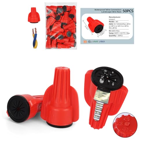
- Outdoor-rated connector set, gel-filled or heat-shrink style
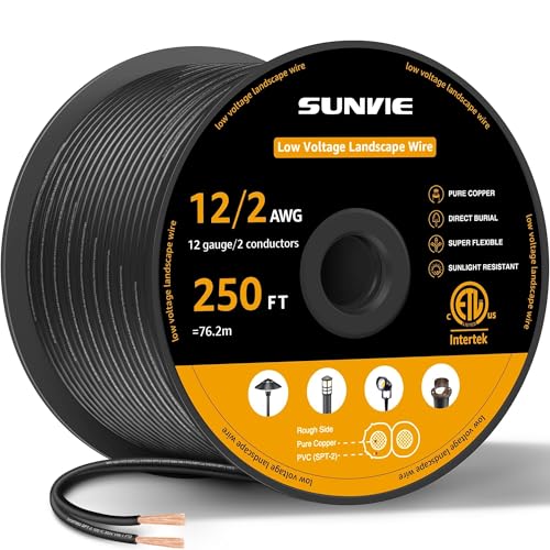
- Direct-bury rated 2-conductor low-voltage cable
- Wire gauge that matches the run, commonly 16, 14, or 12 AWG
- Weatherproof junction box or handhole if the splice must stay accessible
- Transformer with wattage capacity and the correct 12V or 24V output
- Fixture labels or installation sheet for beam angle and input type
Which extension method fits your run?
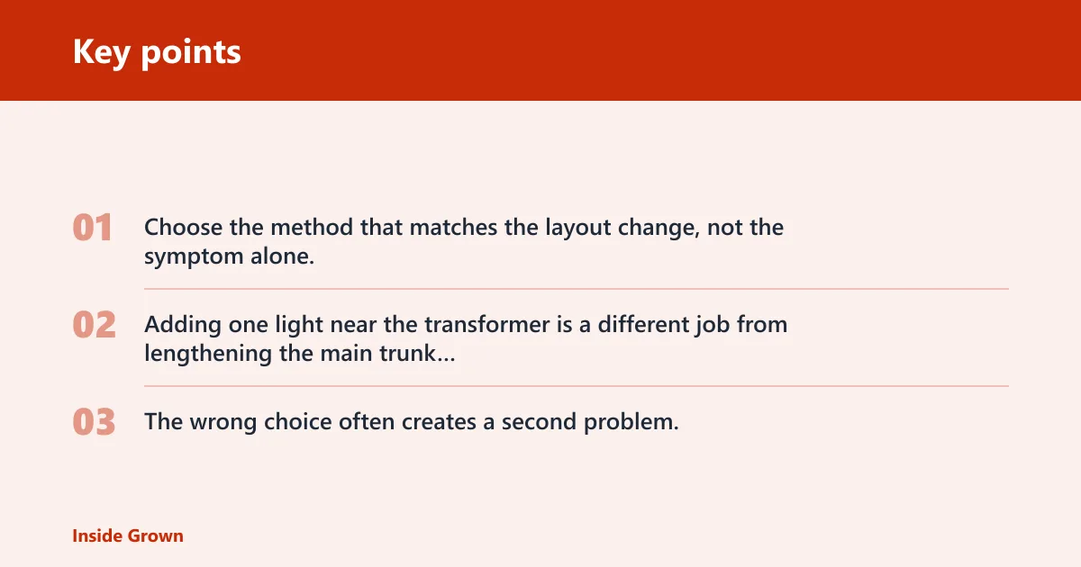
Choose the method that matches the layout change, not the symptom alone. Adding one light near the transformer is a different job from lengthening the main trunk or repairing a dead branch. The wrong choice often creates a second problem, usually voltage drop at the far end or a splice that cannot be buried safely.
| Scenario | Recommended wiring method | When to upgrade wire gauge | Transformer load check | Most likely failure sign |
|---|---|---|---|---|
| Add one fixture near the transformer | Tap the new fixture into the nearest accessible parallel point | Usually not needed if the tap is short and existing cable is already adequately sized | Confirm total watts stay below the transformer rating | Transformer hum or a fixture that is brighter than the rest |
| Extend a short branch | Splice in a direct-bury 2-conductor extension with weatherproof connectors | Upgrade if the added length pushes the far end beyond the 10% voltage-drop target | Add the new fixture watts to the total branch load | End-of-run dimming |
| Lengthen the main trunk | Replace part of the trunk with a heavier-gauge cable or rebuild the trunk path | Often needed when the new total length or wattage pushes the existing gauge too hard | Check both total wattage and the load on each transformer output or zone | Multiple far fixtures dim or flicker together |
| Repair a failing section | Cut out the damaged segment and remake both ends with buried-rated connectors | Only if the repair was exposing undersized wire that caused the failure | Verify the circuit still draws less than the transformer capacity after repair | Dead branch, intermittent power, or corrosion at one splice |
How to size the wire before you splice
Use voltage drop, not guesswork. A simple field check is: voltage drop % = ((transformer voltage – measured fixture voltage) ÷ transformer voltage) × 100. Keep the total drop under 10% for the run. If the far end is already close to that limit, a simple extension will usually make it worse.
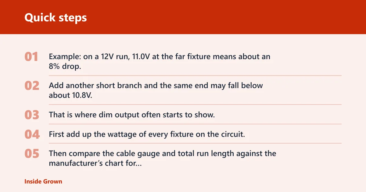
Example: on a 12V run, 11.0V at the far fixture means about an 8% drop. Add another short branch and the same end may fall below about 10.8V, which is about 10% down from 12V. That is where dim output often starts to show.
A simple wattage-and-distance check
First add up the wattage of every fixture on the circuit, including the one you plan to add. Then compare the cable gauge and total run length against the manufacturer’s chart for that wire. If you do not have the chart, treat a long 12V run with multiple fixtures as a warning sign and test the far end before burying anything.
For a rough field check, use the transformer output, total watts, and the farthest cable length together. A higher-wattage load on a long 12V run generally needs heavier wire than the same load on a short 24V run.
When to move up a wire gauge
Move up a gauge when the extension adds enough length or load to push the far end toward dimming. Commonly, 16 AWG suits short, lighter runs; 14 AWG fits moderate runs; 12 AWG is the safer choice when the cable is long or the total wattage is higher. Confirm with the cable maker’s chart for your model.
Suppose a 12V branch already feeds several LED fixtures and the far end looks weak. Replacing only the last splice will not help much if the cable itself is the bottleneck. In that case, a heavier main trunk is the real fix.
How do you connect low-voltage lighting?
Make the connection with outdoor-rated, corrosion-resistant parts. Gel-filled connectors work well where the splice will stay buried. Heat-shrink connectors are a good choice where you want a sealed, compact joint and can shrink them properly. Generic indoor wire nuts are a poor fit for wet soil.
Keep every joint accessible until the circuit has been tested. Low-voltage cable is usually direct-bury rated, but the splice still needs outdoor-rated protection. The cable can go underground. The connector must be chosen for that environment too.
Make a weatherproof splice
Strip only enough insulation for the connector you are using. Join the two conductors firmly and keep polarity consistent if your fixture or transformer requires it. Then tug each conductor lightly to confirm the joint is seated before you bury it.
Tap a new fixture into the run
Use the fixture’s daisy-chain or tap connection only where the manufacturer allows it. Some outdoor light fixtures are meant to accept a direct tap from the cable; others need a short lead or a specific connector. Check beam angle and input voltage on the label before installation.
Keep joints accessible before burial
Test the splice above ground first. Measure voltage at the end fixture, check for flicker, and confirm the transformer load is still within rating. If the result is stable, bury the connection at the depth allowed by the cable and local code.
Step-by-step extension procedure
- De-energize the branch circuit at the breaker before opening any hardwired transformer compartment, then confirm the low-voltage side is dead with a meter.
- Map the existing run and mark the exact extension point, including fixture count, cable gauge, and the length of the new section.
- Check transformer capacity and fixture compatibility. Match 12V or 24V output, AC or DC requirements, and the total wattage after the add-on.
- Choose the wiring path and connector type. Use a short tap for a nearby fixture, a heavier cable for a long trunk, or a repair splice for a failed segment.
- Make the splice, power up, and measure the far end. If the new end drops by more than about 10% or flickers, stop and upsize the cable or shorten the run.
- Bury the joint only after the test passes. If the extension is adding more than one fixture, add them one at a time and recheck after each addition.
For example, if the transformer is rated at about 100 watts and the circuit already uses about 72 watts. Adding two 12-watt fixtures would bring the total to about 96 watts, which may still be within the rating but leaves little headroom. If the far end already looks weak, the better move is a shorter branch or a heavier main trunk, not a third fixture.
Suppose a dead branch returns after a rainstorm. That points more toward a bad splice or water intrusion than a load problem. Cut back to clean copper, remake the joint with a buried-rated connector, and retest before covering it again.
Common mistakes
Overloading the transformer is the easiest mistake to make. Add the wattage of every fixture on the run, then leave some capacity in reserve. If the total is too close to the rating, the transformer may run hot or the lights may sag at night.
Using the wrong connector is the next common failure. Indoor wire nuts are not the same as gel-filled or heat-shrink outdoor connectors. A splice that looks fine above ground can fail after the first wet cycle.
Ignoring end-of-run voltage drop causes dim fixtures and flicker. If the voltage is already low before the extension, the added section should be a redesign, not a simple splice.
Treating a failed branch like a simple add-on wastes time. A dead section needs fault isolation first: test the transformer output, test continuity through the cable, then inspect the splices in order from source to end.
Frequently asked questions
How far can low voltage lighting run?
There is no single distance limit. The practical limit depends on transformer voltage, total fixture wattage, and wire gauge. A 24V run usually tolerates longer distance than a 12V run, but the correct test is still the far-end voltage. Keep drop under 10%.
How to extend a lighting circuit
Choose the extension point first: near the transformer, at a branch, or at the failed section. Then check transformer load, wire gauge, and end voltage. If the new section pushes the far end past 10% drop, rebuild the trunk instead of adding another splice.